The ESP8266 Smart Thermostat run by Home Assistant
A few months ago, I was looking at smart home thermostats in an effort to save a little money on the power bill that seems to just keep coming, as well as, continuing to increase all of the time. I looked at different models from Honeywell, the Ecobee, Nest, and a few others. I noticed one thing about all of them, they all cost way more than they would be able to save me for the foreseeable future. I think a common misunderstanding today is that just because you save money on something, even if you in fact give that money to another company, you are saving. With the smart home thermostats on the market today, this is simply just saving money you would pay the local utility to give it to an electronics manufacturer. With that said, let’s get to the good stuff.
I found a YouTube video from the great DrZzs that talked about using Tasmota to make your own Nest thermostat for a lot less money, and I was intrigued. You can watch the video here. Although I followed the steps outlined in his video I still had to do a little tweaking to make it work for me. However, the materials he recommends are spot on.
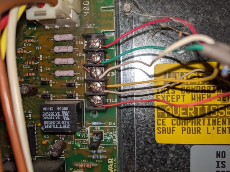
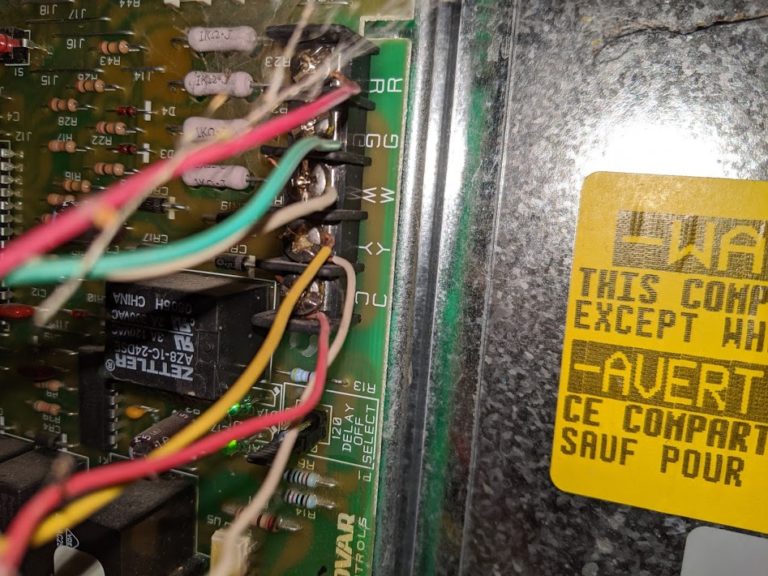
Most home HVAC systems have 4 or 5 wires. For this project, we will only need the first 4 listed below and you will have to do a little investigating to figure out what you have in your home. In general, the wires running to the back of your thermostat in your home will be red (24V power), yellow(cooling), white(heating), green(fan), and if you have a 5th, blue(common). We will not be using the common wire at all for this project. This wire is normally used to power newer thermostats so that batteries are no longer needed. Here is my control board and wiring:
The materials you will need are an ESP8266 or D1 Mini, 3 5V relays with breakout boards, and a USB power source. That’s it. If you have to order all of this from Amazon, you can get it in 2 days for less than $20. If you have a Microcenter nearby then forget about the 2 day wait. You will also need at least one temperature sensor. It doesn’t have to be the same as the ones I use, but I find that the DHT11 and DHT22 models work great. Here is one of mine. It is an ESP8266 running Tasmota connected to a DHT11.
I have found, in my experience, that every now and then an ESP8266 just doesn’t work. Now, I am sure that these are made in the FINEST sweat shops in the world, but do yourself a favor and flash Tasmota before doing any soldering and save yourself a huge headache. You can find the latest release of Tasmota here. The first option in the right side column is the one you want. If you are on Windows, search YouTube for “flash Tasmota esptool.” You will find some videos for Tasmotizer and off you go. If, like me, you are on Linux, congratulations your life is easy. Head over to github and clone the esptool repo. Navigate to the directory where it is stored on the command line and you will be entering 2 commands. I will go ahead and tell you that these commands will require the use of sudo if you don’t want to go to the trouble of adding your user to another group on your system. The commands assume that you do not have any other USBTTY devices plugged into your PC at the same time as the ESP8266. If you are unsure, then run “ls /dev | grep ttyUSB” and you should only see one device listed. If so, then proceed.
sudo esptool.py --port /dev/ttyUSB0 erase_flash
sudo esptool.py --port /dev/ttyUSB0 write_flash 0X00000 /location/of/tasmota.bin
These commands will take a couple of moments to complete and afterwards the ESP8266 will reset. When this is complete, using your phone connect to the WIFI network called “TasmotaXX” and it should prompt you to login to the network. Select the notification to login and fill in the details for your wifi network, and tap on save. FYI, the ESP8266 can only connect to 2.4GHz networks. (The wifi setup can also be done from a laptop or desktop but it is just easier on the phone). Once you click save, you can reconnect your phone to your home wifi network. You will need to figure out the IP address your router assigns to your Tasmota device and save it for later.
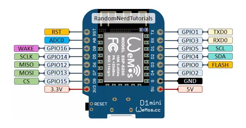
Now that you have your parts, and Tasmota flashed on the ESP8266 let’s have some fun. You will need a little wire and this will require some soldering. On the D1 Mini, you will need to choose 3 GPIO locations and solder a wire to each. Below is a pinout diagram for the D1 Mini. (The pins and their corresponding GPIO locations are the same on other ESP8266 type modules.)
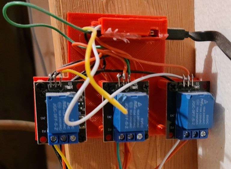
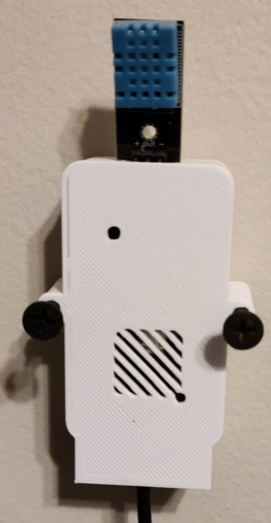
The other end, of each wire, needs to be soldered to one of the three relays. Each relay will also need a 5v and a ground. You can combine these going to the ESP8266. Now, on the screw terminal side of the relay we will be attaching only 2 wires. Each relay needs to have a 24V supply. The other terminal will be either the heat, ac, or fan. What you need to remember from this step is which of those 3 is attached to which relay where the GPIO pin is concerned. You will need this when setting up Tasmota. Here is what mine looks like. (I 3D printed a small board to attach everything, but the wiring is still a little messy.)

Once everything is soldered, connect your USB power to the ESP8266. Then navigate to the device using your favorite browser at http://ipaddressofyourdevice.
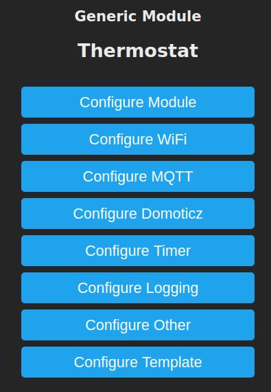
If it doesn’t quite look like this, don’t worry, it will soon.

First, select ‘Configuration’ and then ‘Configure Template.’
From the drop-downs, select ‘Generic (18).’
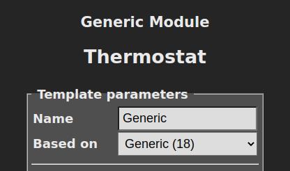
Click save and the device will reboot.
Once it reboots, you will be back at the main menu, and need to select ‘Configuration’ again and then ‘Configure Module.’ Below you will see a screenshot for the way my relays are configured.
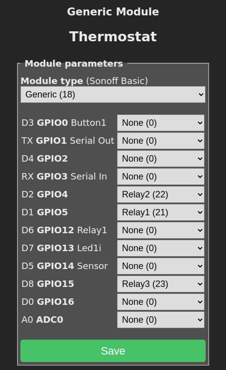
Click Save and once again your device will reboot.
You will need to go back into the configuration of your thermostat and setup MQTT. You will see the option called ‘Configure MQTT’ in the menu and enter the details for your MQTT server.
Now it’s time to setup Home Assistant. First, you will need to add a little YAML to your configuration.yaml file. This will add 3 on/off switches for the heat, ac, and fan. Feel free to name them anything you like.
    - platform: mqtt
      name: "Thermostat Fan"
      command_topic: "cmnd/Thermostat/POWER1"
      state_topic: "stat/Thermostat/POWER1"
      qos: 1
      payload_on: "ON"
      payload_off: "OFF"
      retain: false
    - platform: mqtt
      name: "Thermostat AC"
      command_topic: "cmnd/Thermostat/POWER2"
      state_topic: "stat/Thermostat/POWER2"
      qos: 1
      payload_on: "ON"
      payload_off: "OFF"
      retain: false
    - platform: mqtt
      name: "Thermostat Heat"
      command_topic: "cmnd/Thermostat/POWER3"
      state_topic: "stat/Thermostat/POWER3"
      qos: 1
      payload_on: "ON"
      payload_off: "OFF"
      retain: false
You will also need a climate entry in the config file. Make the adjustments for whatever temperature sensor or sensors you are using. For mine, I have temp sensors around the house and average them so that my heat or air adjusts to the whole home temperature, not just one room. For us, the bedroom is much cooler than the livingroom and adjusting the thermostat for one, made the other uncomfortable.
climate:
  - platform: generic_thermostat
    name: Upstairs Heat
    heater: switch.thermostat_heat
    target_sensor: sensor.average_upstairs_temp
    min_temp: 40
    max_temp: 90
    min_cycle_duration:
      minutes: 5
    initial_hvac_mode: "off"
    target_temp: 69
    away_temp: 60
    cold_tolerance: 0.5
    hot_tolerance: 0.5
  - platform: generic_thermostat
    name: Upstairs AC
    heater: switch.thermostat_ac
    target_sensor: sensor.average_upstairs_temp
    min_temp: 40
    max_temp: 90
    min_cycle_duration:
      minutes: 5
    initial_hvac_mode: "cool"
    target_temp: 74
    away_temp: 76
    cold_tolerance: 0.5
    hot_tolerance: 0.5
    ac_mode: true
After adding this to your configuration, you will need to restart Home Assistant. Afterward, you will need to add a few automations. These will automatically turn on/off the fan when the heat or ac is on. You do not want either to run without the fan, this is bad for your unit. Also, you need to turn off the heat or ac if the other turns on. Running them at the same time would be pointless and waste a whole lot of energy. Here are those automations:
- id: '1580623321766'
  alias: AC On / Heat off
  description: Prevent the Heat From Coming on When the AC is On
  trigger:
  - entity_id: switch.thermostat_ac
    from: 'Off'
    platform: state
    to: 'On'
  condition: []
  action:
  - data: {}
    entity_id: switch.thermostat_heat
    service: switch.turn_off
- id: '1580623321130'
  alias: Heat On / AC Off
  description: Prevent the AC From Coming on When the Heat is On
  trigger:
  - entity_id: switch.thermostat_heat
    from: 'Off'
    platform: state
    to: 'On'
  condition: []
  action:
  - data: {}
    entity_id: switch.thermostat_ac
    service: switch.turn_off
- id: '1580838112819'
  alias: Turn Fan on with AC or Heat
  description: ''
  trigger:
  - entity_id: switch.thermostat_ac
    from: 'off'
    platform: state
    to: 'on'
  - entity_id: switch.thermostat_heat
    from: 'off'
    platform: state
    to: 'on'
  condition: []
  action:
  - data: {}
    entity_id: switch.thermostat_fan
    service: switch.turn_on
- id: '1581110028863'
  alias: Turn Fan Off with AC or Heat
  description: ''
  trigger:
  - entity_id: switch.thermostat_ac
    from: 'on'
    platform: state
    to: 'off'
  - entity_id: switch.thermostat_heat
    from: 'on'
    platform: state
    to: 'off'
  condition: []
  action:
  - entity_id: switch.thermostat_fan
    service: switch.turn_off
Finally, you need to add a lovelace card for your new smart thermostat. I really prefer the Simple Thermostat card that is available in HACS. I find it to be much more functional on touchscreen devices. Here is the yaml for my card:
cards:
  - control: true
    entity: climate.upstairs_ac
    icon: 'mdi:snowflake'
    name: AC
    step_layout: row
    type: 'custom:simple-thermostat'
  - control: true
    entity: climate.upstairs_heat
    icon: 'mdi:fire'
    name: Heat
    step_layout: row
    type: 'custom:simple-thermostat'
type: vertical-stack
If you have any questions, please feel free to email me at jholt@linuxtrucker.com or @jtothehizzy on Twitter. I have been using this setup for almost a year now without a single problem and we rely on it EVERY day. I have setup some automations for when we both leave the house and for when we are on the way home. If your are interested in the configs for these automations, please let me know.